 Photo 1
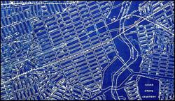
A traditional whiteline street map with intense blue background.
A French chemist, Alphonse Louis Poitevin, discovered in 1861 that images could be reproduced from translucent documents by exposing ferro-gallate coated paper to UV light to develop a stable blue or black dye to emerge. The result was a copy of the original image—usually of a technical drawing, elevation or diagram—with the background tinted dark blue and the image as a whiteline reproduction. Later processes used other photosensitive ferric compounds which evolved into the cyanotype, still producing a blue background and became known as blueprints.
Blueprints are sensitive to the presence of alkalinity and the blue eventually turns brown when alkaline materials are used. They are colored by ferric ferrocynaide which is known to be fairly stable in light and air but additional UV protection is always desirable. So generally avoid heat, UV light and the solvents in spray adhesives.
Cyanotypes
Cyanotypes, also called cyan-blue prints, are a photographic process popular for engineering diagrams well into the 20th century. It was a simple and economical way to duplicate large-scale copies for projects. The chemicals used in developing cyanotypes are sensitive to alkali environments and should not be matted and framed using chemically buffered materials which could accelerate their fading. Another unusual characteristic is its regenerative ability. Prints that have faded due to prolonged exposure to light can often be significantly restored to their original tone by simply temporarily storing them in a dark environment.
Since cyanotypes are light sensitive they require dark storage in neutral (7.0) pH materials making them unsuitable for framing display. Avoid all buffered boards, dry mounting and laminating.
Diazo Prints
A true blueprint has an overall blue color with the drawing in white (photo 1). While whiteprints are just the reverse - white overall with the drawing in blue. In the early 1940s, cyanotype blueprint began to be replaced by diazo & prints, also known as whiteprints, which have blue lines on a white background, and are often called & bluelines. Other comparable dye-based prints are known as blacklines. The process starts with original documents created on a translucent medium such as polyester film, vellum, and bond paper. Any media that allowed some light to pass through worked as a master. Depending on the thickness of the master and the media type, the intensity of the UV & light exposure light would be adjusted.
Photo 1
A traditional whiteline street map with intense blue background.
The original document was laid on top of the chemically-coated side of a sheet of the diazo paper. There were two chambers inside the machine: the first was the exposure area, where the sandwich of the master and diazo paper passed in front of a UV lamp. The light penetrated through the original and neutralized the light sensitive diazonium salt in the area on the sheet that would become the white area on the copy. Once this process was complete, the undeveloped image could often be seen as very light yellow or white marks/lines on the diazo sheet. The original was peeled from the diazo paper and fed into the developing chamber where exposure to ammonia fumes caused additional chemical reaction resulting in the lines changing color from pale yellow to a visible dark color. The range of colors for the lines that resulted were blue, black, or sepia. Diazo printing was one of the most economic methods of document reproduction of large engineering and architectural drawings for many years.
A problem with diazo blueline prints was that with continued exposure to UV light, either natural sunlight or office fluorescent, a blueline would fade over a span of months if indoors, or days if outdoors. Since diazo prints must be protected when not in use, framing them for display should be avoided. Bluelines should not be exposed to the elements, but bluelines kept in flat files in a cool, dry room retain the majority of their lines and are able to be scanned to digital format.
Printers and Plotters
Though diazo prints remain in use in some applications but have been dominantly replaced by dry toner xerographic—electrophotographic—processes. Most recently, designs may be transferred as a digital file directly to a computer printer or plotter (photo 2). Another common modern method of copying is the use of large-format scanners, which digitize the image to be printed. These toner printed images do have a slight heat sensitivity, but do tolerate low temperature short dwell time dry mounting and if laminated any mottling of the toner is camouflaged without alteration of the drawings or diagrams.
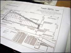 Photo 2
An electrophotographic—xerographic—toner blackline from wide-format plotter.
As print technology develops, the traditional term blueprint has continued to be used to refer to each type of image, but and it is important to understand the differences in order to make the correct decisions over framing and display of them.
If at all possible obtaining a sample of the type of blueprint is the best way to handle working with a contemporary blueprint (photo 3). It is a good practice to ask a lot of questions about any project, and never a sign of inadequacy or lack of professionalism. When samples are available you are much better geared to do the correct thing.
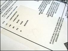 Photo 3
The above blackline sampler was used for testing heat sensitivity and laminate tolerances of 220ºF for 10 minutes.
Prep, Assembly, and Install
Wide-format plotter reprints may end up very large only limited by the width of the printer and any length. The most difficult part of mounting a contemporary blueprint is what to mount it to, and using what process. If it is meant for mounting only, then the surface sensitive toner will require pressure-sensitive adhesives and a roller machine as the best choice. If laminating is desired then either P-S or heat mounting/laminating is fine, but finding a substrate long enough could be a challenge.
The blueprint used in this article is an 18 x 105" blackline map of the railroad line and stations from Bakersfield to Mohave in the late 19th century (photo 4). This blueprint was a working copy that could be replaced, and it was to be displayed at a local museum, so a sample tested for heat and laminate tolerance prior to the main project. It was also decided to save costs by cutting the map into three even pieces so they could be easily and inexpensively mounted and laminated. Each panel was mounted with pure film adhesive at 200ºF in a hot vacuum press to ¼" white Gatorfoam for rigidity. After cooling under a weight to cure the bond and help flatten the boards they were laminated with ultra matte vinyl film laminate from Drytac to control glare (photo 5).
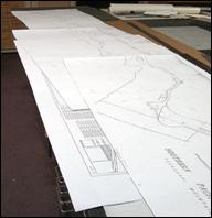 Photo 4
The 18x105" map was cut into three even 18x35" panels for economy and ease of handling and installation.
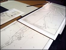 Photo 5
Each panel was mounted with pure film adhesive to ¼" white Gatorfoam for rigidity and laminated with ultra matte vinyl film to control glare.
After mounting and laminating, each of the three panels was edge wrapped on their exposed sides with 1" wide black linen tape, allowing ⅛" to show on the face pulling the extra tape snuggly around to the back. All edges were then aggressively burnished with a bone folder to activate the P-S adhesive. This finished the edges while also covering the uneven hand drawn edge lines making it appear more uniform and professional (photo 6).
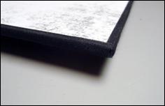 Photo 6
All three panels were edged along only the outer edges with Neschen 1" black linen tape for finishing.
The three 18x35" completed panels were fitted with mitered 1 x ½" clean pine strips built as 16x 33" frame lifters which were painted black and pre-drilled for installation (photo 7). They would accent the overall map by allowing for shadows and drama. The lifters were first nailed to the wall then high tack indoor/outdoor two-sided 3M gray, sponge tape was applied to the affixed lifters and the panels were aligned and snuggly butted against each other to appear as one long unit (photo 8).
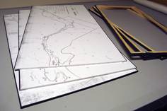 Photo 7
1x½" pine wood was mitered 16x33", painted black and pre-drilled for installation.
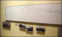 Photo 8
The lifters were nailed to the wall, high tack indoor/outdoor sponge tape was applied and the panels were snuggly butted against each other to appear as one long unit.
A Blueprint
Prior to implementing any design a blueprint, whiteline, blackline or plotter reproduction must be defined and identified by age, process, and potential sensitivities it may have. Keep in mind that early traditional blueprints are indeed light sensitive as it is UV light that activated and created the image in the first place, and that the chemicals that coat the paper to darken it are also often sensitive to alkaline neutrality, so unbuffered materials are mandatory…that said, they should never be framed for permanent display. Only today's plotter digital reproductions are truly safe for mounting, laminating and display.
END
Copyright © 2011 Chris A Paschke
For more articles on mounting basics look under the mounting section in Articles by Subject.
Additional information on all types of mounting is found in:
The Mounting and Laminating Handbook, Second Edition, 2002,
The Mounting And Laminating Handbook, Third Edition, 2008 and
Creative Mounting, Wrapping, And Laminating, 2000 will teach you everything you need to know about getting the most from your dry mount equipment and materials as an innovative frame designer.
All books are available from Designs Ink Publishing through this website.
Chris A Paschke, CPF GCF
Designs Ink
Designs Ink Publishing
785 Tucker Road, Suite G-183
Tehachapi, CA 93561
P 661-821-2188
chris@designsinkart.com